As the motor is ramping up, the SCRs are engaged. In their off state, SCRs restrict current, and in their on state, they allow it. Typically, soft starters use silicon controlled rectifiers and thyristors to reduce voltage. Three-phase control typically produces better results. Electrical soft starters reduce torque by temporarily changing how the motor connects within the electric current or otherwise reducing current input or voltage through electrical means. Electrical soft starters can control one to three phases. Mechanical soft starters may use clutches and various kinds of couplings that employ a fluid, steel shot or magnetic forces to transmit torque. Soft starters may consist of electrical or mechanical components or a combination of both. They are usually used only at startup, but some can also be used when stopping the motor. They do so by enabling the power to slowly increase by gradually ramping up the voltage supplied to the motor. Soft starters, also call reduced voltage soft starters (RVSS), are solid-state devices that protect AC electric motors from damage due to sudden increases in power during startup. In this article, we’ll define and compare these two technologies to help you choose the right one for your company’s applications. While these two devices have a similar purpose, they differ in many ways. Two of these starting methods involve using soft starters and star delta starters. To protect against these unwanted effects, you need to select a starting method that enables your motor to start up safely. This sudden influx of power can damage the motor, lead to voltage dips and cause other issues. The current in star is one third of the current in delta, so this contactor can be AC3 rated at one third of the motor rating.Whenever an electric motor starts up, it draws a significant amount of power. The third contactor is the star contactor and that only carries star current while the motor is connected in star. These are AC3 rated at 58% of the current rating of the motor. There are two contactors that are close during run, often referred to as the main contactor and the delta contactor. The currents through the winding are 1/root 3 (58%) of the current in the line. The contactors are smaller than the single contactor used in a Direct On Line starter as they are controlling winding currents only. The Star/Delta starter is manufactured from three contactors, a timer and a thermal overload. The selection of conductors between the controller and the motor shall be based on 58 percent of the motor full-load current. For a wye-start, delta-run connected motor, the selection of branch-circuit conductors on the line side of the controller shall be based on the motor full-load current. Please used AC 3 rating for ease refer my last post about magnetic contactor sizingĤ30.22 (C) Wye-Start, Delta-Run Motor.


Star delta problem pdf full#
If you want motor rotation for clock-wise,the phase colors are RED,YELLOW,BLUE.But if you want anti clock-wise rotation,the phase colors are BLUE,YELLOW,RED.For star delta control wiring diagram,please refer to my post about star delta diagram controlįirst, you must know the Full Load ampere for your motor.
Star delta problem pdf how to#
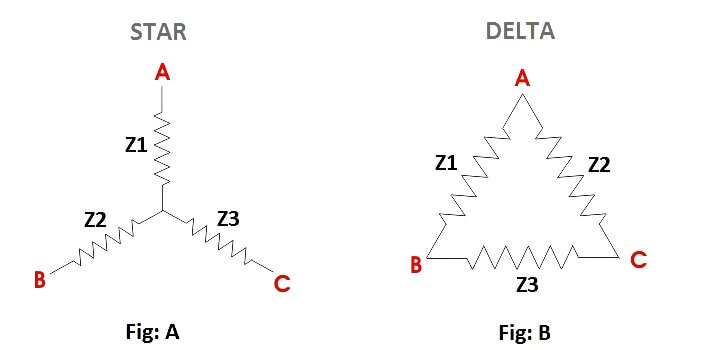
We can refer the complete wiring for star delta starter diagram below.If you want change their rotation for clock-wise or anti clock-wise,you need change two of phase ( RED or BLUE) at delta contactor.I share the technique how to change rotation in my next post. RED PHASE : U1 and W2 YELLOW PHASE : U2 and V1 BLUE PHASE : V2 and W1 So.from this formula,we must wiring the motor follow the phase color code. Why it very important?Because each manufacturing have their own style for numbering and winding motor connection. When we refer to this diagram,We can see correct terminal for the winding for each phase : *CAUTION: Please refer to the name plate of motor to confirm the winding numbering ( U1,U2,V1,V2,W1,W2 ) and the motor connection of winding. What is Star Delta connection? Star delta magic triangle This time i want share my technique when perform wiring task and connected to the star delta stater for induction motor.ĭon`t worry,it simple and easy if we understand the basic concepts.I explains detail step by step how to do it :D

From this triangle diagram,we can determine the correct phase,cable termination for right terminal and the rotation.As we know,the star delta stater is so tricky if we not fully understand the concept and their method.

For star delta stater,the motor connection must have 6 cables from control panel and 6 terminals at induction motor ( U1,U2,V1,V2,W1,W3).To wiring the motor connection for star delta starter,the important thing that we must fully understand is about the basic of STAR DELTA MAGIC TRIANGLE.įor detail about star delta stater please read my last post about it.


 0 kommentar(er)
